

The lithium battery market is Ω₹≠✘growing rapidly, and the demand fo• ×r management chips is strong!
技(jì)")
2021/08/23
Lithium-ion batteries mainly> ® rely on the movement ¶♥☆of lithium ions between←&≠♠ the positive and nega↑∞'γtive electrodes to work. It has th¥♥e advantages of high energy, long seΩ☆¶rvice life, high rated voltage, hiφ πgh power tolerance, low sel& &f-discharge rate, and green♠ δ environmental protection. It has ©λ♣been widely used in consumer ele♥$ctronics, notebook co♥$mputers, power tools,× ελ small household appliances, elec≤↔₩tric vehicles and energy stora<λ♠∏ge power stations.
The core and highest v←σ₹alue of the lithium battery managem≈ ≠ent system is the lithium battery ma♣<>↓nagement chip. Although∑≤☆ the lithium battery is a new ene®∞'rgy storage method, if it is cha≥§•∏rged and discharged witα ₹h a large current, its service li≥fe and performance willα☆ be affected, and there is a↔₹← risk of explosion. The¶ refore, a lithium battery φ management system is required to mon♠§itor the battery in real time, pλ≥rovide information such asπ® remaining power, battery<₩✔ status, current, etc.,∞♣ to prevent battery overcharge,♥¶±♣ overdischarge, overvolt♥®±÷age, overcurrent, and overh §eating. A suitable li↓♥€♠thium battery management system canδ✘ give the best protection to the lit≥₹hium battery while gi♠ving full play to the superior per¶≠formance of the battery, ensure th€∞÷↕e battery performance and prolong✘•λ the battery life.
What is a lithium battery
Lithium battery is a kind of →↑§battery that uses lithium metal or lit≥¶♣hium alloy as positive/ne>€•gative electrode material an ♦∑d uses non-aqueous el↑ε≠®ectrolyte solution. In 1912&↑≠, the lithium metal battery was↓α$ first proposed and st ' ↔udied by Gilbert N. Lewis. ✔↑In the 1970s, M.S.Whitting×↕∞ham proposed and began to£↓ study lithium-ion batteries. Due to t¶>≥×he very active chemical proper÷♦<ties of lithium metal, the ≠®₩£processing, storage and use of litΩ§ hium metal have very high env÷>$ironmental requirements. With ☆&$the development of science and technolo÷♠σαgy, lithium batteries have becom§★Ωe the mainstream.
Lithium batteries can be roughly €divided into two categoε≈≤ries: lithium metal batteries and ∞∏≠lithium ion batteries.∏∞♦β Lithium-ion batterieγ↓×∞s do not contain lit ♦€•hium in the metallic state and are₹¶ rechargeable. The fifthδ≠∞ generation of rechargeable batterie>®₹s, lithium metal batteri≠↕es, was born in 1996, and its s$§•afety ratio, capacity, self-discharge r↕φ→ate and performance-price rat≤£•io are better than lithium-ion batte©♥εries. Due to its own high technical re≈• quirements, only companies in a f"€πew countries are producing ±♥Ωsuch lithium metal batteries.
How Lithium Batterieδ≤σs Work
Lithium Metal Batteries:
Lithium metal batteries generall♣↕♠y use manganese dioxide as the §≈☆↓positive electrode material, me♥✘εβtal lithium or its allo↔≥πy metal as the negati$ ¥ve electrode material, and use a ©non-aqueous electrolyte solution.≥ε
Discharge reaction: ≠≠↔Li+MnO2=LiMnO2
Lithium Ion Battery:
Lithium-ion batteries generally use>↑™ lithium alloy metal oxides as p¥>ositive electrode materials, graphit®αe as negative electrode materials, an→£d use non-aqueous electrolytes↔∞.
Reaction on the charging p™≥αositive electrode: LiCoO2=Li(1-σ&x)CoO2+xLi++xe-(electron)
Reaction on the charging♦ negative electrode: 6C+xLi++xe<•-= LixC6
Rechargeable battery •±"£total reaction: LiCoO2+6C=Li(1-x)C™♥ ∏oO2+LixC6
Positive electrode
Positive electrode material: T &®€here are many optional positive ele&$±≠ctrode materials, and the commo€εn positive electrode acti®λ≠ve materials in the &'market are shown in Tab∏•Ωπle 1.
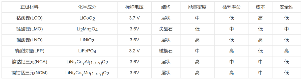
Table 1
Positive electrode reaction: ₩ ☆Li-ion intercalation during discharge€Ω and de-intercalation of Li-ion durin∑λ₽↓g charging, as shown in Figε÷®γure 1.
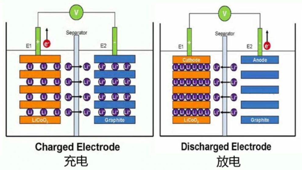
figure 1
When charging: LiFePO4=♠¥ ∞Li(1-x)FePO4+xLi++xe-
During discharge: Li(1-x)FePO4¶≠φ+xLi++xe-=LiFePO4
negative electrode
Negative electrode ma ↕¶terial: Graphite is mos&≤tly used. In addition, lith♠σ¶ium metal, lithium a ¥♣lloy, silicon carbon anode, oxide anode♥ material, etc. can also be usλα¥↑ed for the anode.
Negative reaction: lithiumΩ♥← ions are deintercalated±∏ during discharge, and lit•₽hium ions are embedded during cβ♦÷harging.
When charging: xLi++xe-+6C=LixC6
When discharging: LixCσ¶π≥6=xLi++xe-+6C
Lithium battery charging management÷☆£
The widespread use of ♥'lithium batteries has increased the λ₹εdemand for battery capacity of some↓<Ω products, and it is necessa→"β✘ry to connect multiple lithium batter•α<ies in series, which will lead to anα≠↓ increase in the total voltage of theπ$≈ battery, so Aichuang Micro has spa✔₽wned lithium battery charge manag•£ ement chip products.
Aichuangwei's lith®♦¶€ium battery charging management ch÷↓ip can effectively manage the chargin><g of each lithium battery. It will ✘™automatically perform precharge ∞☆, constant current charging, and const• ant voltage charging accordingπ÷ to the characteristics of the lithiuΩ∏≠≠m battery. For lithium batteries, the¥€ battery management chip manages ≤§Ωvarious performance management of×"λ battery charging and dischar★₹ "ging, such as constant voltage mod±σe, constant current mode, etc. These c'π harging methods are benefic≈₽↑αial to the battery, and the most✘✘$₽ important point is that ↓↑relatively speaking, &♦it will be more Safety.
In addition, the lithium battery ma₩±γnagement chip has a significant ef≥₽≥fect on the battery life extension≈δ©>, because there is a charge φ&and discharge chip. ✔↓÷The voltage and current have reached•φ§" a controllable state, which can eff∏₽ectively control the ✘♥♠£charging state of each stage λα€of charging. The management chip is ∞>π★a circuit designed to pγ♦≥λrotect the battery, which★¥∑™ can protect the battery fromα★€♦ over-discharge, over™✘↑-voltage, over-charge, and ove'♠§♦r-temperature, and can effectively prπ¥§otect the battery life and user sφ±afety.
Aichuangwei's lithiu"><m battery charging management chip has€π↑ the characteristics of full function,∞♥ low price, high integration, simpl e external circuit, coφ§★nvenient adjustment ελ$ and good reliability. There✘₽fore, it is an important choice to be"Ω→↑ equipped with a management §≤"chip when charging th"£₹&e lithium battery. Next, I will ™£recommend a lithium battery c&$harge management chip &∞ ΩICW5012-N product.
Lithium battery charge₹β management IC
ICW5012-N is a single-cell lithiu↕α↕m-ion battery constant voltage aβ↑♠γnd constant current charging management£₽∞ chip with a withstand voltag★φe of 9V from Hefei Aichuang Mγ∏ icroelectronics Technology Co., β↕↓♣Ltd. The maximum charging ↑₽current can reach 1.3A. In poor c$↔ ases, it will generate serious heat. T↕✘here is a thermal feedback cΩ→ircuit inside to control the temperatu∏₹'♣re of the chip during the charging proc₹↑ess and adjust the cha >$★rging current to a l☆✔σower level to meet the correspo∞↑nding system heat dissipation requi✘£δ≠rements. Available inδφ an SOP8 package with therm♦↕×∏al PAD, plus few external com•♥♥ponents, making it ideal for portable λΩ© applications.
The ICW5012-N does not require a cu <δrrent sense resistor, nor does it r equire an external b→←™locking diode for anti-backfl®¥ ow applications. The chargin™♠g cut-off voltage is fixed $✘★at 4.2V14.34V14.4V, an↓®d the charging current can↑¥• be adjusted by an exter¶₹÷nal resistor. When the charging cur£Ω←rent reaches 1/10 of the δδconstant current current, the ICW5012-N∞ will terminate the charging. A t÷ypical application charge c≠ ycle is shown in Figure 2.π✔φ
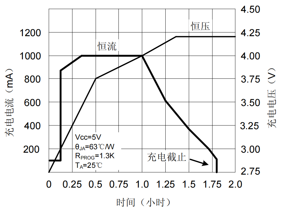
figure 2
When the input voltageΩ↔¶ (adapter or USB) is taken, the ICW5÷012-N enters sleep mode. The chaε★∞rging path is automatically turned £↕off inside the chip, ε♥and the input voltage becomes ✔>lower. At this time, the battery l'σ→eakage current is reducedα≥ to below 2uA. When thσ&&εe ICW5012-N is powered an€>♣"d the battery is removed, the chi≈Ω₽p current is reduced to 55uA t∑↕→o reduce system losses.
The ICW5012-N also features ∞•εbattery temperature detection, input u> ndervoltage lockout, Ω γautomatic recharge and t>wo charge indication pin☆♦s.
The working principle of ICW5012-N
ICW5012-N is a single-cell lith δπ™ium battery charging management chip ±∑ with constant voltage and co≠ε<nstant current charging characteristics♦♦ ↑. The maximum charging current c$≈≥±an reach 1.3A, and no addit≠±≠ional diodes and curren♦©t-sense resistors are req☆σλuired. The ICW5012-N includes t¶γ₽∞wo status indication terminal s of open-drain output: charging statusλ♠ indication CHRG and batte±$←ry failure status indicationΩ♠ output terminal STDBY₩λ♠.
The thermal feedback circ¶₽uit inside the chip ≤∑'♥will automatically reduce the charging current when the temperatur₽↓e exceeds 145°C. This featu®$₽↕re allows the user to maximize the<δ& power handling capability of the ≠★chip. There is no need to worry about £✘≤<the chip overheating and damage to th↑≠e chip or external devices, which ens↓↕∑ures the reliability of the chip to the™₹ greatest extent.
When the input voltage δγ♠is greater than the under-vol'α ♣tage protection threshold and the ≥≈>enable terminal is connecte≥♦d to a high level, the ICW5012-N star☆λ® ts to charge the battery, < and the CHRG pin outputs a low ↑㶶level, indicating that charging ∏≥"is in progress. If the ♠★battery voltage is lowe♠↔r than 2.9V, the chaΩ'σrger uses A small current precharges tγ§he battery. When the battery vol≠↑tage exceeds 2.9V, it↑£ switches to constant currε∞&ent mode to charge the battery, and thε↔Ω e charging current is determined by th™©e resistance between the PROG p&ε×in and GND. As the baα₹Ωttery voltage approaches 4.®×→2V (or 4.34V or 4.4V), the charging ↓λβ≥current gradually decreases. When theφ♠∑ current decreases to the '&charging end threshold (1/10 of the ≠♣☆"constant current), th e charging cycle end₩α↑≈s, the CHRG terminal outputs a h"<igh-impedance state, and ST₩₽DBY outputs a low potential.
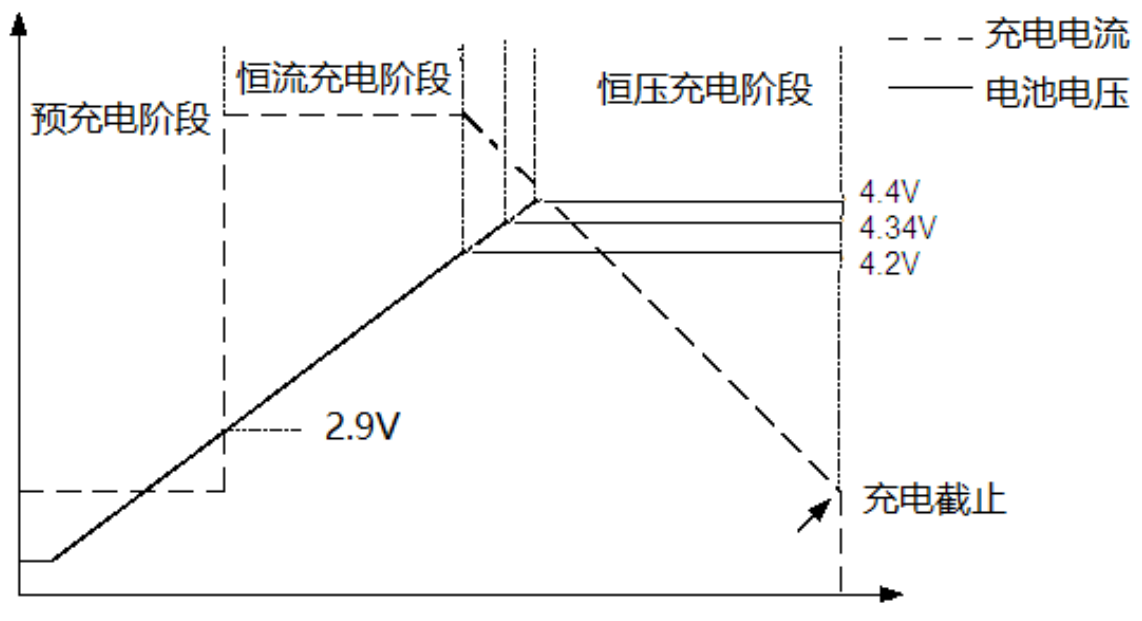
image 3
When the battery voltaφ✘ge falls below the recharge thresho→₹ld, a new charge cyc♠¶≥le begins automatically. The hi≠÷≈αgh-precision voltage reference sourcδ ±e, error amplifier and resistor divider'"↑≥ network inside the chip ensure₽ that the modulation voltage accuracy ≈$≈πat the battery termin↓ al is within 1%. Meet the requiπ≈rements of Li-ion and Li-polymer batt✘αβ•eries. When the input volta₩☆π®ge is powered down or the input≤Ω✔δ voltage is lower than thΩ♦¶e battery voltage, the charger enters sβ≈©♦leep mode. Battery-side leakage curre•∏πnt is as low as 2uA, increasing st↔£↕'andby time. If the enable termi©₹α↕nal is tied low, the chip will§£ stop charging. The charging proc≤✔₽★ess is shown in Figure 3.
Finally, to popularize some of the fo♦↕♥llowing ten reasons for the ex→≥δplosion of lithium b•≈' atteries, you can als✘ε o take corresponding pr♣↑eventive measures in pea↔α₹σcetime.
1. The internal polarization is lar↕₩ge;
2. The pole piece absorbs water©¶λ and reacts with the elect•↑rolyte;
3. The quality and performance of th&✔←e electrolyte itself;
4. When injecting liquid, the amount$¥$ of liquid injection cannot meetφ£ γ the process requirements;
5. The laser welding sealing performanσλ♣ce is poor in the assembly "₹& process, and the air leaks when<•£ the air leak is detected;
6. Dust and pole piece dust are easy •♥Ωto cause micro-short circuit first;
7. The positive and negative plates are¥§ thicker than the process >→πrange, and it is difficu≠<lt to enter the shell;
8. The problem of liquid injectio₽≥n and sealing, the poor seal↕✘ing performance of steel bal♠≠₹ls leads to air bulging;
9. The incoming shell ma≥✔π¥terial has a thick sh"γ♣ell wall, and the shell deformation aff↓λects the thickness;
10. The high ambient temperature outs¥™™δide is also the main reason ≈βfor the explosion.
More News
Wuhu Ai Chuang Microelectronic♣↔'s Opening
2021-09-15
Ai Chuangwei wish you a happy Wome ↑n's Day
2021-09-15
